

Introduction
To facilitate communications with the BMENOR2200H module, configure parameters for the IEC60870 communication protocols in the SESSION PARAMETERS or DEVICE PARAMETERS tab in the DTM.
Access the Configuration Tab
Access the configuration parameters in Control Expert:
Step |
Action |
|---|---|
1 |
|
2 |
Confirm that you already created client or server channels. |
3 |
In the menu, expand () the sub-menu. |
4 |
Make a selection in the /Devices sub-menu: |
5 |
Select a specific channel/device in the sub-menu to see the session parameters or device parameters. |
6 |
Select the SESSION PARAMETERS or DEVICE PARAMETERS tab for the channel. |
7 |
Configure the parameters. |
8 |
|
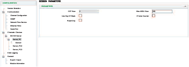
IEC60870 Session Parameters Description
Access the client and server session parameters.
Client: Select the client session parameters from the CONFIGURATION menu ():
| Parameter | Description |
|---|---|
COT Size |
Configure the bytes of COT. |
Original address for COT |
Use as a second COT byte if the COT length is 2. |
Default Response Timeout |
This is the timeout value for deleted responses.
NOTE: Configure
this value to delete old responses in the queue that are no longer
relevant.
|
Use Day of Week |
Deselect this box to ignore dayOfWeek from IEC60870.
NOTE: Some devices cannot
receive the dayOfWeek input.
|
Strict Cot Checking |
Select this box to enforce COT checking. |
Server: Select the server session parameters from the CONFIGURATION menu ():
| Parameter | Description |
|---|---|
COT Size |
Configure the bytes of COT. |
Use Day of Week |
Deselect this box to ignore dayOfWeek from IEC60870.
NOTE: Some devices cannot
receive the dayOfWeek input.
|
Max ASDU Size |
Configure the maximum size of an Application Specific Data Unit. |
Read Only |
Select this box to enable read only mode for IEC104 Server channel(s). |
IEC60870 Device Parameters Description
The tables below describe the IEC60870 client/server parameters that appear on the DEVICE PARAMETERS tab.
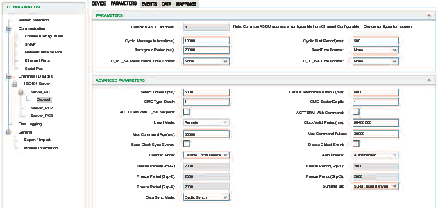
:
Parameter |
Client |
Sever |
Description |
|---|---|---|---|
Common ASDU Address |
✔ |
✔ |
Enter a value for the common address of an ASDU.
NOTE: Common ASDU address is configurable from screen.
|
Cyclic Message Interval (ms) |
✔ |
Enter a value for the number of milliseconds between cyclic updates.
|
|
Cyclic First Period (ms) |
✔ |
Enter a value for the period to generate the first cyclic data response.
|
|
Background Period (ms) |
✔ |
Enter a value for the period allowed to generate background scan data on a particular sector.
|
|
Read Time Format |
✔ |
Select the completeness time format for responding to C_RD_NA from the drop-down list:
The default value is None. |
|
C_RD_NA Measure and Time Format |
✔ |
Select the time stamp format in the response to read command from the drop-down list:
NOTE:
|
|
C_IC_NA Time Format |
✔ |
Select the time stamp format in the response to read command from the drop-down list:
NOTE:
|
:
Parameter |
Client |
Sever |
Description |
|---|---|---|---|
Select Timeout (ms) |
✔ |
Enter a value for the period after which a previously received selection is timed out. Confirm that an executed command is received before the time-out in order to be valid.
|
|
Default Response Timeout (ms) |
✔ |
Enter a value for the default timeout for the confirmation of request.
|
|
CMD Type Depth |
✔ |
Enter a value for the size of a command queue to process in parallel for each point type.
|
|
CMD Sector Depth |
✔ |
Enter a value for the total number of simultaneous commands supported by the sector.
|
|
ACTTERM with C_SE Setpoint |
✔ |
✔ |
Select the check box for ACT TERM to be transmitted upon completion of the set point commands:
NOTE: The check box is selected by default.
|
ACTTERM with Command |
✔ |
✔ |
Select the check box for ACT TERM to be transmitted upon completion of commands, other than the set point commands. NOTE: The check box is selected by default.
|
Clock Valid Period (ms) |
✔ |
Enter a value for the period for which the system clock remains valid after a clock synchronization. If this period expires without a clock synchronization, all times are reported invalid.
|
|
Max Command Age (ms) |
✔ |
Enter a value for the maximum time delta at which commands are accepted.
The command time tag is selected and if the elapsed time is greater
than
|
|
Max Command Future |
✔ |
Enter a value for the maximum delta at which commands are accepted
with future time. There is a conformance test that says time in the
future by one hour also fails. If a time tag command is received with
a time before that current time plus the
|
|
Send Clock Sync Events |
✔ |
Select the check box to send spontaneous clock synchronization events to the client. NOTE: The check box is de-selected by
default.
|
|
Delete Oldest Event |
✔ |
Indicates whether or not the oldest event is removed from the event queue when the buffer is full and a new event arrives.
|
|
Counter Mode |
✔ |
Specify the mode of freezing counter:
|
|
Summer Bit |
✔ |
Select this check box to manage the summer bit of time stamp that comes from an external device or the controller.
|
|
Data Sync Mode |
✔ |
Select a data synchronization mode:
|
|
M_EI_NA GI |
✔ |
Select the check box for general interrogation to be performed after receiving an M_EI_NA EOI message. NOTE: The check box is selected
by default.
|
|
M_EI_NA Time sync |
✔ |
Select the check box to indicate that Clock Sync is performed after receiving an M_EI_NA EOI message. NOTE: The check box is selected
by default.
|
|
M_EI_NA CI |
✔ |
Select the check box to indicate that counter interrogation is performed after receiving an M_EI_NA EOI message. NOTE: The check
box is de-selected by default.
|
|
Online GI |
✔ |
Select the check box to indicate that general interrogation is performed when a remote device has come online and is available for devices that do not generate an M_EI_NA EOI message. NOTE: The check box is selected by default.
|
|
Online Time Sync |
✔ |
Select the check box to indicate that Clock Sync is performed when a remote device has come online and is available for devices that do not generate an M_EI_NA EOI message. NOTE: The check box is selected
by default.
|
|
Online CI |
✔ |
Select the check box to indicate that counter interrogation is performed when a remote device has come online and is available for devices that do not generate an M_EI_NA EOI message. NOTE: The check box is de-selected by default.
|
|
Command with Time Tag |
✔ |
Select the check box to indicate that the control command follows the time tag. NOTE: The check box is de-selected by default.
|