

Introduction
Configure the IEC60870-5-101 and IEC 60870-5-104 communications for your module in the Control Expert DTM.
Basic Parameter Configuration
Configure the CLIENT or SERVER channels:
Step |
Action |
|---|---|
1 |
|
2 |
In the open CONFIGURATION window, expand (+) Communication and select Channel Configuration. NOTE: The Channels/Devices menu item cannot
be expanded because there are no configured channels.
|
3 |
Select the appropriate tab:
|
4 |
Select the Add New button to view the ADD NEW CHANNEL configuration parameters. |
5 |
Configure the parameters according to the new channel parameter descriptions below. |
6 |
Select the Add button to see the newly configured channel in the table. NOTE: The Devices menu can now be expanded because there is at least
one configured device. All configured devices appear in this menu.
|
7 |
After you create a server channel on the SERVER tab, repeat steps 1-6 to create the corresponding client channel on the CLIENT tab (or vice versa). NOTE: Only one client and one server are supported.
|
8 |
NOTE: When you create the first channel, the expandable Channels/Devices sub-menu appears on the CONFIGURATION screen.
|
9 |
Repeat steps 1-8 to create additional channels while observing these limitations:
|
Basic Parameter Descriptions
These parameters in the ADD NEW CHANNEL fields are available for the IEC60870-5-101/104 client and server channel configurations:
Field |
Client |
Server |
Description |
|---|---|---|---|
Channel Name |
✔ |
✔ |
Assign a name to the server. NOTE: The web pages use the Channel Name parameter
to identify the configuration that is applied to this channel. Therefore,
assign an identical Channel Name when you configure cyber security
settings.
|
Protocol |
✔ |
✔ |
IEC60870-5-104 client IEC60870-5-104 server IEC60870-5-101 client IEC60870-5-101 server |
IP Address |
✔ |
Enter the IP address of the server with which the client communicates. NOTE: This field applies to IEC60870-5-104 only.
|
|
Dest Port |
✔ |
Define the destination port. NOTE: This field applies
to IEC60870-5-104 only.
|
|
IP Filter |
✔ |
When you select the IP Filter field, the IP Filter Panel dialog box opens. Enter the IP address of the remote device. Select the Ok button. NOTE: This field applies
to IEC60870-5-104 only.
|
|
Local Port |
✔ |
Define the local port for network communications.
|
|
Redundant Group |
✔ |
Select None, 1, 2 from the drop-down list. NOTE: This field applies
to IEC60870-5-104 only.
|
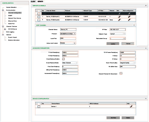
Advanced Parameter Configuration
After you create a channel using the instructions above, the new channel appears in the table on the CLIENT or the SERVER tab. You can configure ADVANCED PARAMETERS for the channel. These advanced parameters are global settings that are implemented on all server or client channels.
Step |
Action |
|---|---|
1 |
Select Channel Configuration from the Communication menu. |
2 |
Select the appropriate tab:
|
3 |
Select a row in the table. |
4 |
Select the Advanced Settings button to view the ADVANCED PARAMETERS table. NOTE: Depending on your Control Expert window size, you may
have to scroll down in the Client or Server tab to see
the ADVANCED PARAMETER fields.
|
5 |
Configure the parameters according to the advanced parameter descriptions below. |
6 |
|
Advanced Parameter Descriptions
Field |
Client |
Server |
Description |
|---|---|---|---|
T1 Ack Period (ms) |
✔ |
✔ |
Enter a value for timeout of waiting for ACK to a transmitted APDU. T1 of server should be greater than T2 of client.
|
T2 S Frame Period (ms) |
✔ |
✔ |
Enter a value for time to wait before sending supervisory APDU ACK.
|
T3 Test Period (ms) |
✔ |
✔ |
Enter a value for ldle before sending TEST APDU.
|
K Value |
✔ |
✔ |
Enter a value for the max unacknowledged transmitted APDUs.
|
First Char Wait (ms) |
✔ |
✔ |
Enter a value for the minimum time between reception and transmission.
|
W Value |
✔ |
✔ |
Enter a value for the max unacknowledged received APDUs.
|
Rx Buffer Size |
✔ |
✔ |
Enter a value for the receive buffer size of serial port (bytes).
|
Offline Poll Period (ms) |
✔ |
✔ |
Enter a value for the period to re-establish transfer of an offline session.
|
Max Queue Size |
✔ |
Enter a value for the maximum request message number with a specific application specific data unit (ASDU) type and destination matching an outstanding request that will be queued on a client.
|
|
Incremental Timeout (ms) |
✔ |
✔ |
Enter a value for the incremental application layer time-out.
|
Inhibit command when CPU stop |
✔ |
Select this box to stop sending commands when the controller stops. |
|
Event Backup Enable |
✔ |
Specify whether to back up events when a power outage is detected. By default, the check box is deselected. |
|
Event Buffer Sync Enable |
✔ |
|
|
Event Buffer Sync Ports |
✔ |
Select network path to transfer event sync data.
|