

Introduction
To facilitate communications with the BMENOR2200H module, create data points for the IEC60870-5-101/104 communication protocols in the DATA MAPPINGS tab in the DTM.
Access the Configuration Tab
Access the configuration parameters on the DATA MAPPINGS tab in Control Expert:
Step |
Action |
|---|---|
1 |
|
2 |
Confirm that you already created client and/or server channels. |
3 |
In the CONFIGURATION menu, expand (+) the Channels sub-menu. |
4 |
Make one of the following selections in the Channels/Devices sub-menu:
|
5 |
Select the desired device in the sub-menu. |
6 |
Select the DATA MAPPINGS tab for the channel. |
7 |
Configure the data mapping parameters. |
8 |
|
IEC60870 Data Mappings
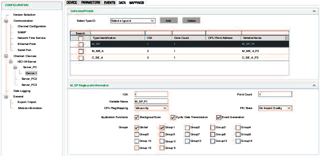
Edit the data point configuration on the DATA MAPPINGS tab:
Step |
Action |
|---|---|
1 |
Select a type ID in the Select Type Id drop-down list. |
2 |
Select the Add button to configure the data object type. |
3 |
Configure the data object type. Depending on the data object type and the selected protocol profile, different configuration fields are required to define a data object mapping item. |
4 |
|
IEC60870 Data Mapping Parameters
This table describes parameters that appear on the DATA MAPPINGS tab for both client and sever:
Client & sever Parameter |
Description |
|
|---|---|---|
| IOA | Indicates the information object address of the object. |
|
| Point Count | Indicates the number of objects defined. The IOA of each object defined. The IOA of each object is in sequence from the first object address. |
|
| Variable Name | Indicates the variable name. |
|
| CPU Reg Mapping | Indicates the choice of the stored time or flag; follows the value in the controller Device DDT variable:
|
|
| Threshold | Indicates the default threshold value for M_ME_A/M_ME_B point to trigger event. |
|
Indicates the default threshold value for M_ME_C point to trigger event. |
||
| Low Limit | Indicates the low limit value for M_ME_A/M_ME_B point to trigger event. |
|
Indicates the low limit value for M_ME_C point to trigger event. |
||
| High Limit | Indicates the high limit value for M_ME_C point to trigger event. |
|
Indicates the high limit value for M_ME_A/M_ME_B point to trigger event. |
||
| Add CMD_STATUS | Specify the CMD_STATUS variable name. |
|
This table describes parameters that appear on the DATA MAPPINGS tab for sever:
Sever Parameter |
Value Scope |
Description |
|
|---|---|---|---|
| Associate Point Number | 104 max.: 16777215 101 max.: based on IOA size |
Starting point number of the point. |
|
| Channel Mask | Check boxes |
For each check box, specify the channel number to clear object group (dependent on the channel configuration). |
|
| Default Qualifier |
|
Default qualifier of the command if the controlling station does not specify a qualifier. |
|
| Freeze Period | 0...4294967295 |
Specify the width of the pulse (ms). |
|
| M_ME_X Point Number | 1...16777215 |
Specify the associated M_ME_X point parameter. |
|
| PLC State | No Impact Quality Impact Quality |
Specify whether the quality of monitoring points are impacted by the PLC state. |
|
| Type | (command types) |
Select a command type. |
|
| Short Pulse Duration | 0~4294967295 ms |
Indicates the short pulse duration for C_SC/C_DC/C_RC control point. |
|
| Long Pulse Duration | 0~4294967295 ms |
Indicates the long pulse duration for C_SC/C_DC/C_RC control point. |
|
| Need Select | Check box |
Indicates the need to select before operation for C_SC/C_DC/C_RC/C_SE_A/C_SE_B/C_SE_C control command. |
|
| Cdc Mode |
|
Indicates the pulse recovery state for C_DC command. In determinate state mode, it recovers to the previous on (2)/off (1) state. In indeterminate state mode, it recovers to the fixed intermediate (0) state. |
|
| Global 1/2/3/4/5/6/7/8/910/11/12/13/14/15/16 | Check box |
Defines the data object group responding to the interrogation command from the client. It can be a combination of options. |
|
This table describes parameters that appear on the DATA MAPPINGS tab for client:
| Client Parameter |
Value Scope |
Description |
||
|---|---|---|---|---|
| Operation Mode |
|
Indicates the operation mode for C_SC/C_DC/C_RC/C_SE_A/C_SE_B/C_SE_C control command. |
||
|
Indicates the active/deactive operation for the C_IC/P_AC point. |
|||
|
Indicates the operation mode for C_CI control command. |
|||
| Qualifier |
|
Indicates the qualifier for C_SC/C_DC/C_RC control command. When it is received, a C_SC/C_DC/C_RC command with ‘default qualifier,’ the server operates the command with this configured qualifier. |
||
G/1/2/3/4/5/6/7/8/9/10/11/12/13/14/15/16 |
Indicates the interrogation group for C_IC control command. |
|||
1/2/3/4/G |
Indicates the counter interrogation group for C_CI control command. |
|||
|
Indicates general reset or event clear for C_RP control command. |
|||
|
Indicates the parameter type to set for P_ME_A/P_ME_B/P_ME_C point. |
|||
| Read Number | 1...16777215 |
Indicates the information object address of the point to be read. |
||
| Qualifier |
|
Indicates the parameter type to set for P_ME_A/P_ME_B/P_ME_C point. |
||
Event Routing |
Route Channel | Disable/Enable |
Indicates whether the event routing function is disabled or enabled. |
|
| Route Session | 0 | Indicates the session number to route. |
||
| Route Sector | Server device list |
Indicates the device to route. |
||
| Route Point | 1...16777215 |
Indicates the information object address to route. |
||
| Routing Offline | Valid Quality |
Use any available routing channel connection. |
||
Invalid Quality Without Events |
Set the flag to offline when the routing channel is offline. |
|||
Invalid Quality With Event: |
|
|||
| Background Scan | Check box |
Indicates the background scan is enabled. (The check box is selected.) |
||
| Cyclic Data Transmission | Check box |
Indicates the cyclic data transmission is enabled. (The check box is selected.) |
||
| Event Generation | Check box |
Indicates that events for points can be configured. |
||
Clearing Events in the Server
Clear_Events supports a new point type which clears the event buffer in DNP3 and IEC60870-5-101/104 servers. It enables the user to clear the events buffer in a local or remote SCADA through mapping memory.
To create Clear_Events for these servers, select Data Mapping.
When the value of the Clear_Events register changes, the BMENOR2200H module clears the events of the object group in the configuration.
Parameter |
Value Scope |
Definition |
|---|---|---|
| Object Group | All ObjectsBinary InputDouble InputBinary CounterAnalog InputBinary OutputAnalog Output | Specifies the object group whose event is cleared o. demand |
| Variable Name | — |
Indicates the name of the located register. |
Event Queue Setting Page
Configure the parameters on the tab to map the event queue status to the Device DDT registers in the controller. Each event queue status consumes one three-byte register.
Access the event queue configuration in Control Expert:
Step |
Action |
|---|---|
1 |
Expand: IEC10• Server<ServerName><DeviceName> |
2 |
Make a selection in the pull-down menu on the tab |
3 |
Select the button to view the parameters for the selected type: NOTE: When the Control Expert window is active, you can hover the cursor over any field to see
a description of the functionality and the available range of values.
|
4 |
|