

Introduction
To facilitate communications with the BMENOR2200H module, create data points for the DNP3 communication protocol in the tab in the DTM.
Access the Configuration Tab
Access the configuration parameters on the tab in Control Expert:
Step |
Action |
|---|---|
1 |
|
2 |
Confirm that you already created client or server channels. |
3 |
In the menu, expand () the /Devices sub-menu. |
4 |
Make a selection in the /Devices sub-menu: |
5 |
Select a specific channel in the sub-menu. |
6 |
Select the tab for the channel. |
7 |
Configure the data mapping parameters. |
8 |
|
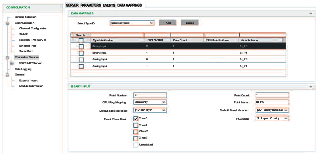
DNP3 Data Mappings
Using a as an example, edit the data point configuration on the tab:
Step |
Action |
|---|---|
1 |
At , select a type ID. NOTE: For this example, select .
|
2 |
Click to see the name ‘Binary Input’ in the column. |
3 |
Select the table row that corresponds to the new binary input to see the configuration options. |
4 |
Modify the parameters. NOTE: When the Control Expert window
is active, you can hover the cursor over any field to see a description
of the functionality and the available range of values.
|
5 |
|
Exchangeable Controller Data Object
| WARNING | |
|---|---|
Implement the data dictionary in Control Expert:
Step |
Action |
|---|---|
1 |
Open the (). |
2 |
Expand () the menu: |
3 |
Select the setting to see the and columns. |
4 |
In the column, find the row and select the corresponding box in the column. NOTE: Select this box when you
program the PLC application. Otherwise, unlocated variables may not
be mapped to RTU data points. However, a compiled application consumes
more memory when the data dictionary is included, which can have an
impact on unlocated variables that are implemented in RTU solutions.
|
5 |
|
Unlocated variables can be exchanged between the controller and the BMENOR2200H module after you define and manage the memory map of the controller to exchange data with the module.
The controller data objects are mapped and only linked for the BMENOR2200H module’s purpose.
Data Exchange
To sustain a high rate of data exchange, the user can define the BMENOR2200H module’s RTU memory for data objects in a sequential ARRAY data type to group points with the same settings.
Use consecutive point numbers (0, 1, 2, 3...) in DNP3 request fragments. Inconsecutive point number will cause some DNP3 points unavailable to work.
Predefined Command List
The required input fields are requested to define a predefined command item for DNP3 client/DNP3 NET client.
Static Variation Name of DNP3
Data object type |
Static variation |
|---|---|
Binary Input |
g1v1 Binary In |
g1v2 Binary In Flag |
|
Double Input |
g3v1 Double In |
g3v2 Double In Flag |
|
Binary Output |
g10v1 Binary Out |
g10v2 Binary Out Flag |
|
Binary Counter |
g20v1 32bit Counter |
g20v2 16bit Counter |
|
g20v5 32bit Ctr No Flag |
|
g20v6 16bit Ctr No Flag |
|
Frozen Counter |
g21v1 32bit Frozen Ctr Flag |
g21v2 16bit Frozen Ctr Flag |
|
g21v5 32bit Frozen Ctr Flag Time |
|
g21v6 16bit Frozen Ctr Flag Time |
|
g21v9 32bit Frozen Counter |
|
g21v10 32bit Frozen Counter |
|
Analog Input |
g30v1 32bit Analog In |
g30v2 16bit Analog In |
|
g30v3 32bit AI No Flag |
|
g30v4 16bit AI No Flag |
|
g30v5 Short Float AI |
|
Analog Input Deadband |
g34v1 16bit AI Deadband |
g34v2 32bit AI Deadband |
|
g34v3 Short Float AI Deadband |
|
Analog Input Dband_Ctrl |
g34v1 16bit AI Deadband |
g34v2 32bit AI Deadband |
|
g34v3 Short Float AI Deadband |
|
Analog Output |
g40v1 32bit Analog Output |
g40v2 16bit Analog Output |
|
g40v3 Short Float AO |
|
Read_Group |
— |
Read_Class |
— |
Write_Octet_String |
— |
Freeze_Counter |
— |
Unsolicited_Class |
— |
Time_Sync |
— |
Restart |
— |
Octet String |
g110 Octet Strings |
Integrity_Poll |
— |
Gen_Events |
— |
Clear_Events |
— |
Mapping Tables
Depending on the data object type and the selected protocol profile, different configuration fields are required to define a data object mapping item. The tables below describe the available parameters for each selection in the pull-down menu on the client and server tabs.
Binary Input
This table describes the DNP3 net client parameters that appear on the tab when you select a in the tab:
Client Parameter |
Description |
|
|---|---|---|
|
Indicates the start number of the point. NOTE: Confirm that the DNP3 point number starts at 0 and is contiguous in server mode. If this
is not applied, the nonconsecutive points cannot work normally.
|
|
|
Indicates the number of points. |
|
|
Choose a source for the event time stamp and flag:
|
|
|
Name of the unlocated register |
|
|
Select the static variation for the data point. |
|
|
|
|
|
Point number to route. (This point number appears in the server side but cannot be modified on the server side.) |
|
|
Defines the event class of points. |
|
|
Indicates the default event variation for data point. |
|
|
Specify the flag when the routing channel is offline:
|
|
This table describes the DNP3 net server parameters that appear on the tab when you select a in the tab:
Server Parameter |
Description |
|
|---|---|---|
|
Indicates the start number of the point. NOTE: The DNP3 point
number starts at 0 and is contiguous in server mode. If this is not
the case, the nonconsecutive points do not work normally.
|
|
|
indicates the number of points. |
|
|
Choose a source for the event time stamp and flag:
NOTE: Select one of these values to implement SOE
for time stamping.
|
|
|
Name of the unlocated register |
|
|
Select the default static variation for the data point. |
|
|
Select the default event variation for the data point. |
|
|
Defines the event class of points. |
|
|
Specify the flag when the routing channel is offline:
|
|
Analog Input
This table describes the client data mapping parameters for analog input types:
Client Parameter |
Description |
|
|---|---|---|
|
Indicates the start number of the point. NOTE: Confirm that the DNP3 point number starts at 0 and is contiguous in server mode. If this
is not applied, the nonconsecutive points cannot work normally.
|
|
|
Indicates the number of points. |
|
|
Choose a source for the event time stamp and flag:
|
|
|
Select the static variation for the data point. |
|
|
Name of the unlocated register |
|
|
Specify a deadband variable name. |
|
|
Name of the unlocated register when is selected. |
|
|
|
Enable or disable the routing of the channel number. |
|
Define the point number to route. |
|
|
Defines the event class of points. |
|
|
Indicates the default event variation for data point. |
|
|
Specify the flag when the routing channel is offline:
|
|
This table describes the server data mapping parameters for analog input types:
Server Parameter |
Description |
|
|---|---|---|
|
Indicates the start number of the point. NOTE: Confirm that the DNP3 point number starts at 0 and is contiguous in server mode. If this
is not applied, the nonconsecutive points cannot work normally.
|
|
|
Indicates the number of points. |
|
|
Defines the event class of points.
In client, confirm that |
|
|
Select the default static variation for the data point. |
|
|
Select the default event variation for the data point. |
|
|
Choose a source for the event time stamp and flag:
NOTE: Select one of these values to implement SOE
for time stamping.
|
|
|
Deadband value of the analog input |
|
|
Use low and high range for the percentage of deadband calculation when the check box is selected. |
|
|
Lowest value in the range when the check box is selected. |
|
|
Highest value in the range when the check box is selected. |
|
|
Name of the unlocated register |
|
|
Specify the flag when the routing channel is offline:
|
|
|
Specify a deadband variable name. |
|
|
Name of the unlocated register when the check box is selected. |
|
Binary Output
This table describes the client data mapping parameters for binary output types:
Client Parameter |
Description |
|
|---|---|---|
|
Indicates the start number of the point. NOTE: Confirm that the DNP3 point number starts at 0 and is contiguous in server mode. If this
is not applied, the nonconsecutive points cannot work normally.
|
|
|
Indicates the number of points. |
|
|
The selected operation mode |
|
|
Specify the control code used by the CROB:
NOTE: Refer to the description of binary output
behavior.
|
|
|
Specify the width of the pulse (ms). |
|
|
Name of the unlocated register |
|
|
Specify the CMD_STATUS variable name. |
|
Server data mapping parameters for binary output types:
Server Parameter |
Description |
|
|---|---|---|
|
Indicates the start number of the point. NOTE: Confirm that the DNP3 point number starts at 0 and is contiguous in server mode. If this
is not applied, the nonconsecutive points cannot work normally.
|
|
|
Indicates the number of points. |
|
TCC |
It is used to create Trip Close Control Code of CROB. If it is enabled,
the odd point in this configuration is close output and the following
point is trip out, when outstation receives close or trip command.
Be sure that the point count should be even if enabled.
|
|
Short Pulse Duration |
Indicates the pre-configured pulse duration of the server |
|
|
Select the default static variation for the data point. |
|
|
Select the default event variation for the data point. |
|
|
Specify the flag variable name. |
|
|
Name of the unlocated register when the check box is selected. |
|
|
Specify the flag when the routing channel is offline:
|
|
|
This prefix for the variable name
is followed with an underscore ( Example: |
|
|
The only available option for the binary output is %MW. |
|
|
This is the start %MW address in the controller. This field applies only to located variables. To create a variable without a %MW address, use the value -1. Considerations:
|
|
The is applied in the client, which records the latest value, state (flag), and time stamp.
Analog Output
This table describes the client data mapping parameters for analog output types:
Client Parameter |
Description |
|
|---|---|---|
|
Indicates the start number of the point. NOTE: Confirm that the DNP3 point number starts at 0 and is contiguous in server mode. If this
is not applied, the nonconsecutive points cannot work normally.
|
|
|
Indicates the number of points. |
|
|
Selected operation mode |
|
|
Select the default static variation for the data point. |
|
|
Name of the unlocated register |
|
|
Specify the CMD_STATUS variable name. |
|
This table describes the server data mapping parameters for analog output types:
Server Parameter |
Description |
|
|---|---|---|
|
Indicates the start number of the point. NOTE: Confirm that the DNP3 point number starts at 0 and is contiguous in server mode. If this
is not applied, the nonconsecutive points cannot work normally.
|
|
|
Indicates the number of points. |
|
|
Defines the event class of points. |
|
|
Select the default static variation for the data point. |
|
|
Select the default event variation for the data point. |
|
|
Deadband value of the analog point |
|
|
Name of the unlocated register |
|
|
Specify the flag variable name. |
|
|
Name of the unlocated register when the check box is selected. |
|
|
Specify the flag when the routing channel is offline:
|
|
|
The prefix for the variable name
is followed with an underscore ( The final variable name follows this format:
Example: |
|
|
The only available option for the analog output is %MW. |
|
|
This is the start %MW address in the controller. This field applies only to located variables. To create a variable without a %MW address, use a start address of the type float/32 bit. A
valid analog output type value is an even number. Use address Considerations:
|
|
The is applied in the client, which records the latest value, state (flag), and time stamp.
Floating point values (scientific notation) can be entered for the .
Behavior of a Binary Output
This configuration depends on the selection you made in the field in the binary output client parameters.
The configuration applies , pulse on, and .
Depending on the situation, three control types are available for binary outputs. This table shows examples of Trip/close point numbers in the client and server sides for the BMENOR2200H module.
CROB sent in DNP3 client |
Point number in DNP3 client |
Point number in DNP3 server |
|---|---|---|
Close/Pulse on (double mode) |
n n |
n |
Trip/Pulse on (double mode) |
n + 1 |
|
Close/Pulse on (single mode) |
n |
first element of n |
Trip/Pulse on (single mode) |
second element of n |
Refer to these trigger mechanisms for the corresponding type of control code:
Op type field |
Trigger mechanism |
Description |
|---|---|---|
Pulse_on |
any value change (0...65535) |
pulse on if value change |
Latch_on |
even-to-odd value
change, for example:
|
latch on |
Latch off |
odd-to-even value change, for example:
|
latch off |
Close/Pulse_on |
even-to-odd value change, for example:
|
pulse on for close output |
Trip/Pulse_on |
odd-to-even value change, for example:
|
pulse on for trip output |
Long and Short Pulses of Binary Outputs
This configuration depends on the selection you made for these parameters in the binary output client parameters:
: It is the pulse duration setting of the client.
: It is the pre-configured pulse duration of the server.
Set Measured Value
Apply analog input deadband () to set deadband of measured value. The parameters of the measured points are activated immediately after the DNP3 server receives the request from the DNP3 client.
For DNP3 , there is no qualifier to set as it only applies the parameter . Set the static variation and point number at the same setting of the analog input. Analog input is applied both on the DNP3 client and the DNP3 server. The DNP3 server uses it to store the current value which is reported in the response of read requests, the DNP3 client uses it to display the current value which can be controlled by the server through the analog input control block.
This configuration depends on the deadband settings you made in these fields:
(analog input client parameters)
(analog input server parameters)
(analog input server parameters)
Octet String Mapping for DNP3
In DNP3, Octet String applies to group 110. It supports read, write, and response function codes.
For the BMENOR2200H module, the octet string splits into two types of points, input points and output points.
The client uses a Read_Group command to read the Octet String.
Octet String points are input points.
Write Octet String points are output points.
Octet String points with protocol variable access are input points for the DNP3 client.
Octet String points with controller variable access are output points from the controller.
maximum: 255 characters
default: 16 characters
Event Generation
Access the event command configuration in Control Expert:
Step |
Action |
|---|---|
1 |
Follow the directions to configure a server channel. |
2 |
Expand (+) . |
3 |
Select one of these items from the pull-down menu on the tab: |
4 |
Select the button to view the parameters for the selected type:
NOTE: When the Control Expert window is active, you can hover the cursor over any field to see
a description of the functionality and the available range of values.
|
5 |
|
Clearing Events in the Server
Clear_Events supports a new point type which clears the event buffer in DNP3 and IEC60870-5-101/104 servers. It enables the user to clear the events buffer in a local or remote SCADA through mapping memory.
To create Clear_Events for these servers, select Data Mapping.
When the value of the Clear_Events register changes, the BMENOR2200H module clears the events of the object group in the configuration.
Parameter |
Value Scope |
Definition |
|---|---|---|
| Object Group | All ObjectsBinary InputDouble InputBinary CounterAnalog InputBinary OutputAnalog Output | Specifies the object group whose event is cleared o. demand |
| Variable Name | — |
Indicates the name of the located register. |
DNP3 Event Parameters
The event-generation parameters in the following tables are available after you create an instance of the corresponding type ID. Select the instance of Generate Events or Clear Events in the Data Mappings table to view the parameters.
Generate Events parameters:
Parameter |
Description |
|---|---|
Point Number |
Start point number of the point (min: 0, max: 65535, default: 0) |
Point Count |
Number of the points (min: 0, max: 7000, default: 1) |
Object Group |
Object group to read (default: binary input) |
Point Name |
Name of located or unlocated register (default: –, forbidden symbol: {} “ [], max length: 50) default: CE_P0_P0 |
Add CMD_STATUS |
selected: Specify a CMD_STATUS variable name. |
deselected: A CMD_STATUS variable name is not specified. |
Clear Events: parameters:
Parameter |
Description |
|
|---|---|---|
Object Group |
Object group to read (default: binary input) |
|
Point Name |
Name of located or unlocated register (default: –, forbidden symbol: {} “ [], max length: 50) default: CE_P0_P0 |
|
Add CMD_STATUS |
selected: Specify a CMD_STATUS variable name. |
|
deselected: A CMD_STATUS variable name is not specified. |
||
Channel Mask |
Main Channel |
Select the appropriate Channel
Mask box to specify the channel number to clear an object
group.
NOTE: This functionality is configuration dependent.
|
Virtual Channel-1 |
||
Virtual Channel-2 |
||
Virtual Channel-3 |
||
Event Queue Setting Page
Configure the parameters on the tab to map the event queue status to the Device DDT registers in the controller. Each event queue status consumes one three-byte register.
Access the event queue configuration in Control Expert:
Step |
Action |
|---|---|
1 |
Expand: Channels/Devices<DNP3 NET Server><ServerName> |
2 |
Make a selection in the pull-down menu on the tab |
3 |
Select the button to view the parameters for the selected type: NOTE: When the Control Expert window is active, you can hover the cursor over any field to see
a description of the functionality and the available range of values.
|
4 |
|