

Primary DTM
Use the primary DTM to configure the IP address settings, which the primary DTM will use when communicating with the HART module.
The HART module is designed to receive its IP address settings from the FDR server in the CPU, so configure the DHCP settings in the primary DTM.
Accessing Module IP Address Properties
Follow these steps to access the page for the HART analog I/O module, where you can input IP address settings:
Step |
Action |
|
|---|---|---|
1 |
In the , right-click the M580 CPU. |
|
2 |
Select from the context menu. Result: The primary DTM configuration window opens. |
|
3 |
Use the tree control on the left side of the DTM configuration window to navigate to a HART analog I/O module that you previously added to the configuration: 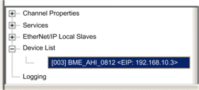 |
|
4 |
Select the tab to access the IP address configuration settings: 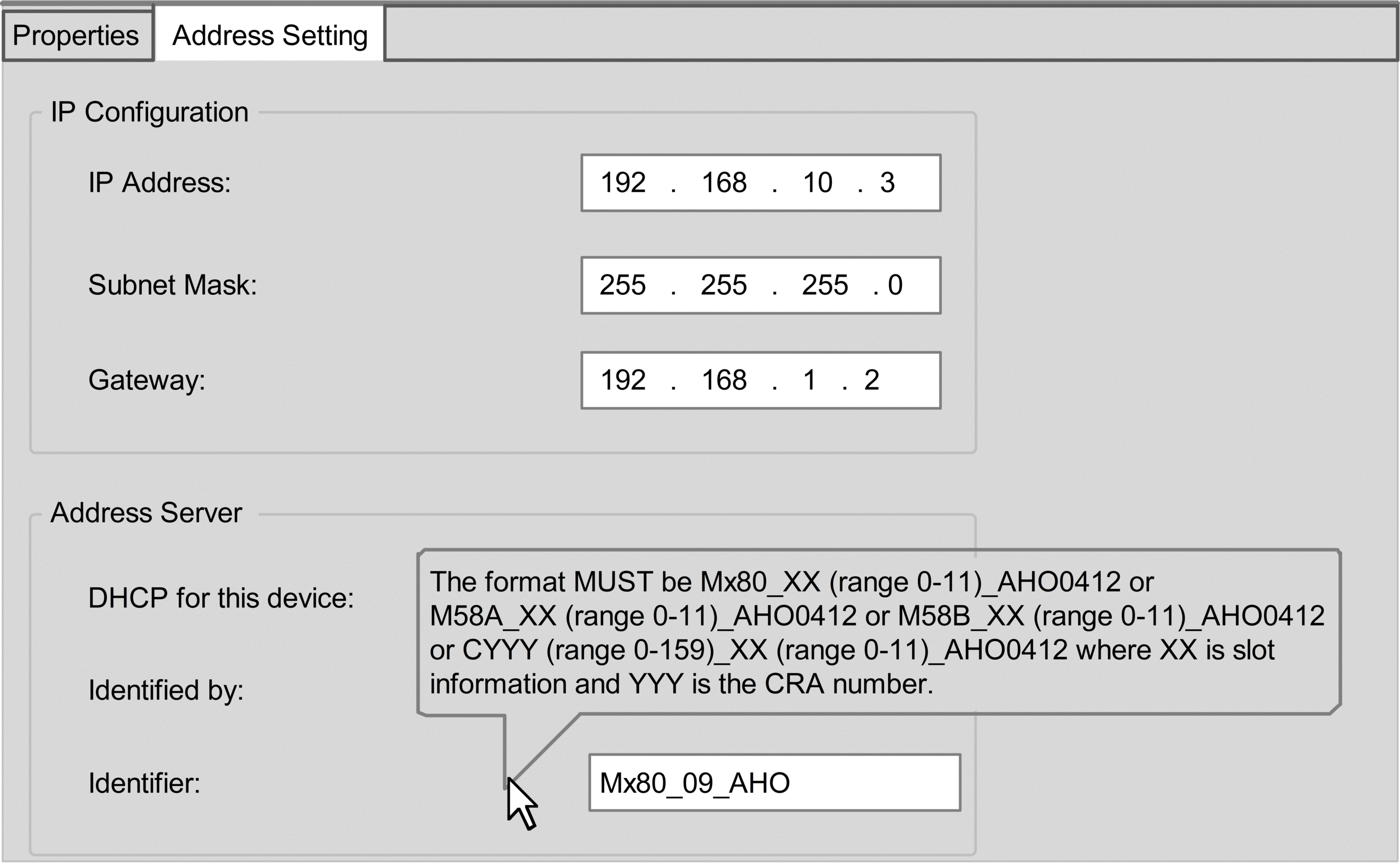 |
|
5 |
Use the following fields to configure IP address settings for the selected HART analog I/O module: |
|
IP Address |
Enter the IP address that the FDR server in the CPU serves to the selected HART analog I/O module. |
|
Subnet Mask: |
Accept the default value. |
|
Gateway: |
Accept the default value. |
|
DHCP for this device |
Select . |
|
Identified by |
Select . |
|
Identifier |
Enter the identifier for the selected HART analog I/O module. NOTE: Refer
to the following topic: Creating a Device Name for DHCP.
|
|
6 |
Click . |
|
7 |
In the CPU primary DTM, select in the navigation tree. |
|
8 |
Confirm that the is correct. NOTE: Control Expert uses this
IP address to communicate with the CPU.
|
|
Creating a Device Name for DHCP
When the DHCP client service is enabled in the primary DTM, the HART analog I/O module uses the identifier to request an IP address from the FDR server in the CPU. Create the identifier by concatenating the Rack ID and Slot Number values to the Module Name, as follows:
= __
The components of the concatenated include the following:
Parameter |
Description |
|---|---|
Rack ID |
A 4-character field that identifies the rack used for the module:
|
Slot Number |
A field that identifies the position of the module in the rack. |
Device Name |
Use the following module names for the purpose of generating a :
|
Sample device name identifiers could be:
Mx80_02_AHI0812 for a BMEAHI0812(H) module located at slot 2 of a main rack.
M58A_03_AHI0812 for a BMEAHI0812(H) module located at slot 3 of a primary Hot Standby rack
M58B_04_AHO0412 for a BMEAHO0412(C) module located at slot 4 of a standby Hot Standby rack
C001_05_AHO0412 for a BMEAHO0412(C) module located at rack 1, slot 5 of a remote I/O rack