

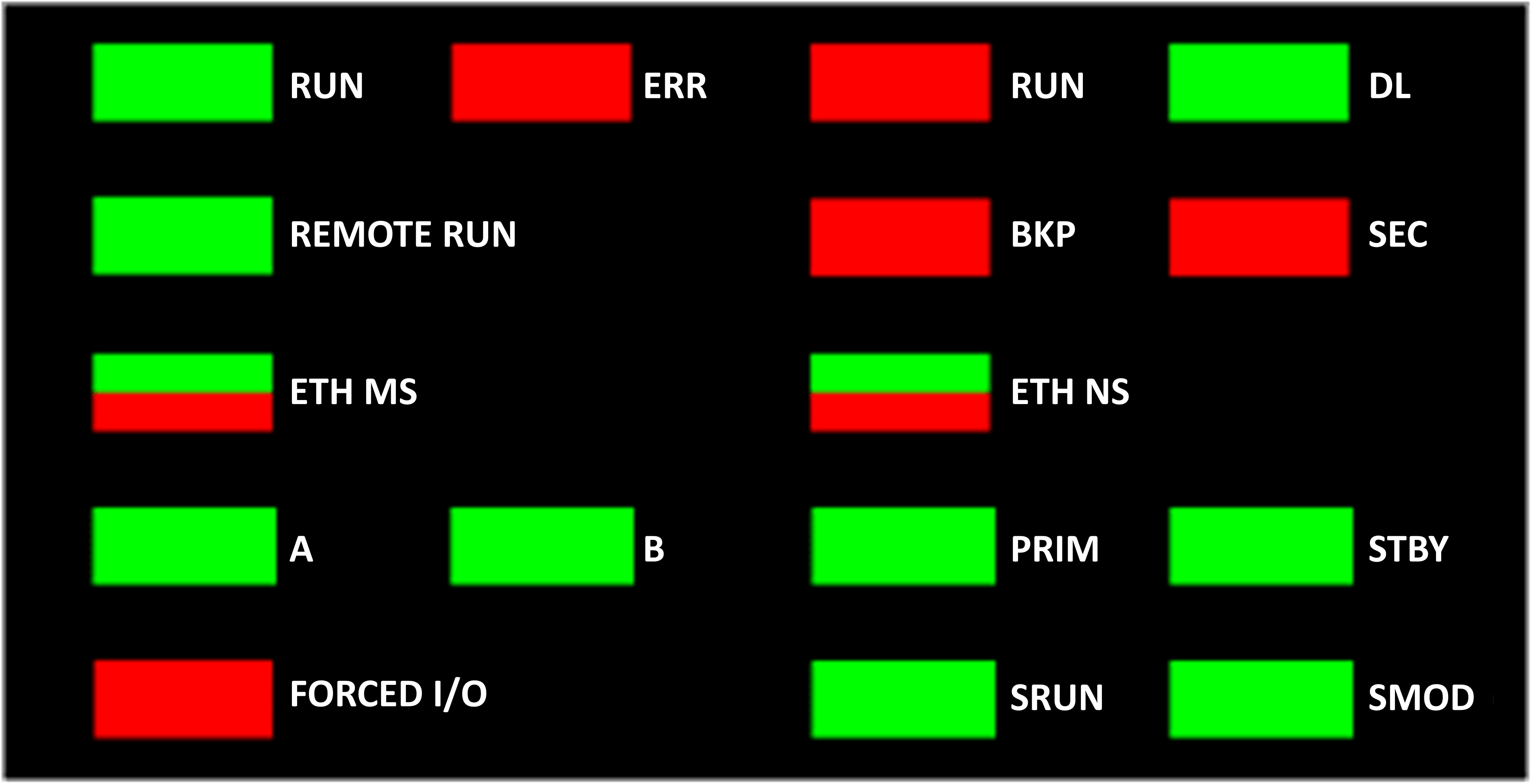
LED Panel
The front face of a BMEH58•040 Hot Standby controller presents the following LED panel, which you can use to diagnose the state of the M580 Hot Standby system:
For a description of the safety controller LEDs and , refer to the topic LED Displays for the M580 Safety Controller and Copro in the Modicon M580, Safety System Planning Guide.
For a presentation of LED diagnostics for safety-related controllers, refer to the topic M580 Safety Controller LED Diagnostics in the Modicon M580, Safety Manual.
Hot Standby Panel LEDs
Use the BMEH58•040 Hot Standby controller A and B LEDs to identify the controller configurations, as set by the rotary switch on each controller:
LED |
||
|---|---|---|
A |
B |
|
Local controller is A, remote controller is B |
ON |
OFF |
Local controller is B, remote controller is A |
OFF |
ON |
Both controller configured as A |
Flashing |
OFF |
Both controller configured as B |
OFF |
Flashing |
Local rotary switch on CLEAR |
Flashing |
Flashing |
In the Hot Standby Panel LED diagnostic presentation, above:
The local controller is the controller whose LEDs you are observing, which could be either A or B.
The remote controller is the controller whose LEDs you are not observing, typically located in a remote location.
For example, consider the design where the two controllers are physically distant but communicate via a tunnel, with a controller located at each tunnel terminus. In this case, the local controller is the one in front of you; the remote controller is the one at the distant end of the tunnel. But, if you move to the other end of the tunnel, the formerly remote controller becomes the local controller and the original local controller becomes the remote controller. By contrast, the designations of controller A and controller B do not change.
Use the BMEH58•040 REMOTE RUN LED on the local controller to identify the operational status of the remote controller:
REMOTE RUN LED |
Remote controller State |
|---|---|
ON |
RUN |
Flashing |
STOP |
OFF |
Indeterminate |
Use the BMEH58•040 PRIM, and STBY LEDs to identify the operational status of the local and remote controller:
LED |
Controller State |
||
|---|---|---|---|
PRIM |
STBY |
Local controller |
Remote controller |
ON |
OFF |
Primary |
Standby |
ON |
Flashing |
Primary |
Wait |
Flashing |
Flashing |
Wait |
Indeterminate |
OFF |
OFF |
Wait |
Indeterminate |
OFF |
ON |
Standby |
Primary |
Hot Standby Link LED
A Hot Standby link LED is located on the front of the BMEH58•040 controller:
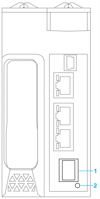
1 SFP socket for copper or fiber-optic Hot Standby link connection
2 Hot Standby link LED
Use this LED to diagnose the state of the Hot Standby link:
Status |
Color |
Description |
|---|---|---|
on |
green |
The port is communicating with the remote controller. |
flashing |
green |
The port is configured and operational, but a Hot Standby link is not made. |
off |
— |
The Hot Standby link is not configured or is not operational. |
Ethernet Port Connector LEDs
Each Ethernet RJ45 connector presents a pair of LED indicators:
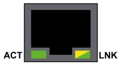
The Ethernet connector LEDs indicate the following states:
LED |
Color |
State |
Description |
|---|---|---|---|
ACT |
Green |
Flashing |
Data is being transmitted over the link. |
Off |
No transmission activity is occurring. |
||
LNK |
Green |
On |
Link speed = 100 Mbit/s. |
Yellow |
On |
Link speed = 10 Mbit/s. |
|
Green / Yellow |
Off |
No link is established. |
Non-Hot Standby Panel LEDs
Refer to the following topics for additional information regarding non-Hot Standby LEDs:
LED Diagnostics for M580 Standalone Controllers in the Modicon M580 Hardware Reference Manual for standalone, non-safety–related LEDs.
M580 Safety Controllers LED Diagnostics in the M580 M580 Safety Manual, for safety–related LEDs.