

Introduction
The BMEAHO0412(C) eX80 HART analog output module supports 4-20 mA analog communication and HART digital communication on each of 4 output channels.
Both the eX80 HART analog output module and the 4-20 mA current loop are powered by the backplane.
Output Slew Rate
When the HART function is enabled, the slew rate of each analog output is automatically limited. As a result, the output slew does not unintentionally trigger the HART receiver.
When HART is... |
The output slew rate is automatically set to... |
|---|---|
Enabled |
0,8...0,9 mA/ms |
Disabled |
|
Overshoot/Undershoot Control
Each output on the BMEAHO0412(C) eX80 HART analog output module operates over a range of 4-20 mA. You can map up to three current ranges for each output.
Upper and lower tolerance detections are enabled regardless of overflow/underflow control.
Depending on the range specified, the module checks for overflow and verifies that the measurement falls between a lower and an upper threshold:

Designation |
Description |
|---|---|
Nominal range |
The specified measurement range |
Overshoot area |
The range of values located above the upper threshold |
Undershoot area |
The range of values located below the lower threshold |
The values of the thresholds are configurable independently from one another. Both the default values, and the maximum and minimum configurable values are as follows:
Range |
BMEAHO0412(C) Range |
|||||
|---|---|---|---|---|---|---|
Undershoot Area |
Nominal Range |
Overshoot Area |
||||
Default setting |
–2,500 |
–801 |
–800 |
10,300 |
10,301 |
10,625 |
Minimum / Maximum |
–32,768 |
... |
... |
... |
... |
32,767 |
Writing Outputs
The application can provide the outputs with values using the standard display (in %, to 2 decimal places):
Type of Range |
Display |
|---|---|
4-20 mA |
from 0 to 10,000 (0% to 100%) |
It is also possible to define the range of values within which measurements are expressed, by selecting:
the minimum nominal value corresponding to the minimum value for the range: 0 %.
the maximum nominal value corresponding to the maximum value for the range (100 %).
The lower and upper thresholds can be integers between –32,768 and +32,767.
Output Behavior on Program Interruption
In the event the BMEAHO0412(C) HART analog module detects an event that stops program execution, depending upon the seriousness of the interruption, each of the outputs undertakes one of the following responses:
apply its fallback/maintain position
be forced to 0 mA
Output behaviors:
If the detected event is... |
The output response is... |
|---|---|
Task in STOP mode, or program missing |
Fallback/Maintain (channel by channel) |
Communication interruption |
Fallback/Maintain (channel by channel) |
Configuration detected error |
0 mA (all channels) |
Internal detected error in module |
0 mA (all channels) |
Output value out of range (undershoot/overshoot) |
Value saturated at the defined limit (channel by channel) |
Open circuit |
Maintain (channel by channel) |
Module hot swapping (processor in STOP mode) |
0 mA (all channels) |
Reloading program |
0 mA (all channels) |
Behavior during initial power-up and power off |
0 mA (all channels) |
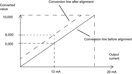
Actuator Alignment
The process of alignment involves the elimination of an observed systematic offset, around a specific operating point, for a given actuator. Actuator alignment compensates for a detected variation that is linked to the process. Replacing a module does not require a new alignment. However, replacing the actuator or changing the actuator operating point requires a new alignment.
Conversion lines are as follows:
The alignment value is editable from a programming console, even if the program is in RUN mode. For each output channel, you can:
view and modify the desired measurement value
save the alignment value
determine whether the channel already has an alignment
The alignment offset may also be modified through programming.
Channel alignment is performed on the channel in standard operating mode, without any effect on the channel operating modes.
The maximum offset between measured value and desired (aligned) value may not exceed +/-1,500.