

Introduction
Refer to the LED indicators to monitor the status and performance of these items:
BMENOR2200H module LEDs (below)
Module LED Descriptions
The module LED indicators are located on the front of the BMENOR2200H module. The LEDs provide information on:
module status (run, error, downloading)
Ethernet network communications
RTU communications
SD memory card state
serial communications
cyber security mode
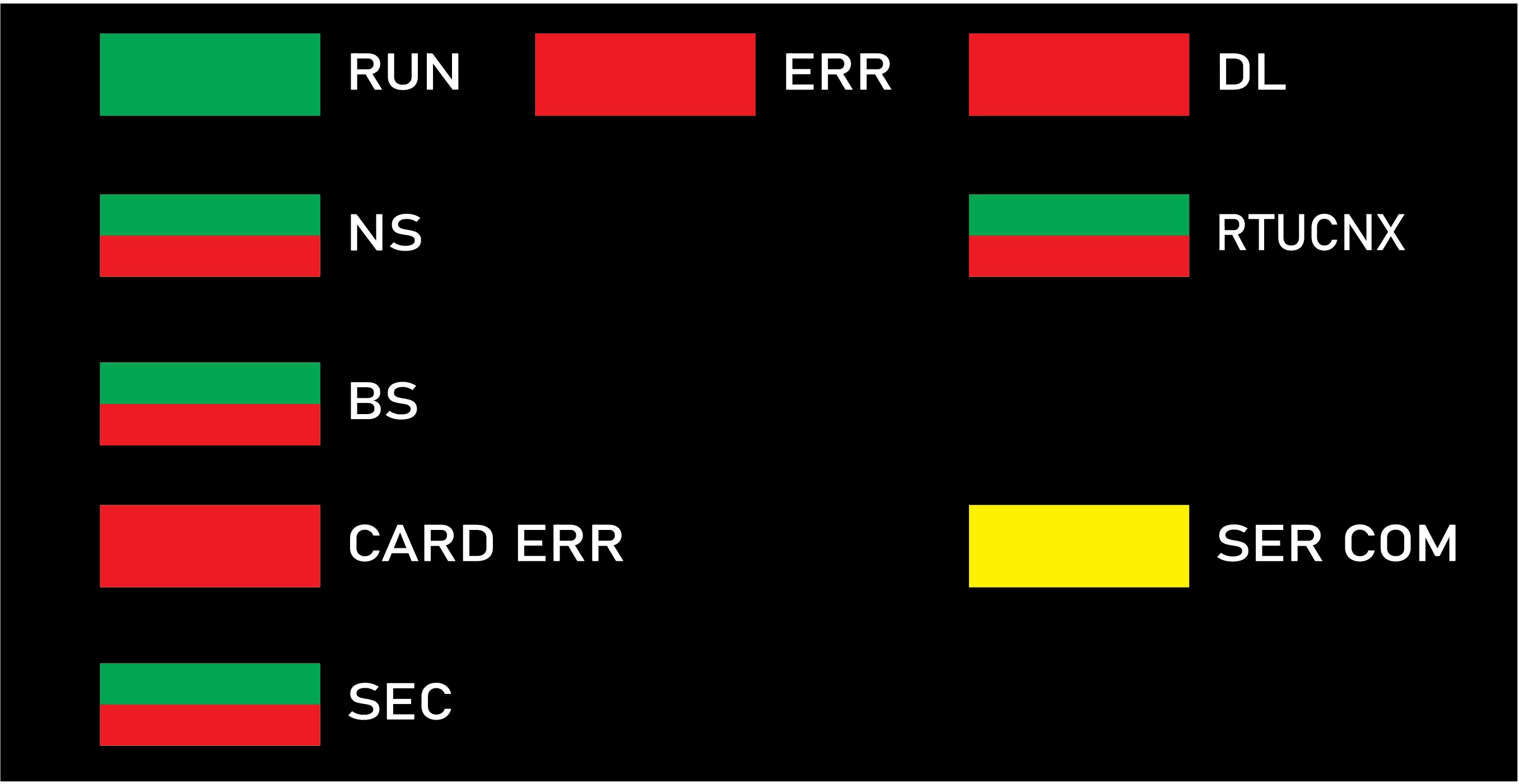
This is the LED display on the front of the BMENOR2200H module:
The LEDs can be in these states:
on: steady on
off: steady off
flashing: alternate (250 ms on, 250 ms off)
The module status is indicated by the color and state of the LEDs:
Label |
Color |
Pattern |
Indication |
|---|---|---|---|
RUN: operational state |
green |
on |
The module is operating and configured. |
flashing |
The module is blocked by a detected software error. |
||
off |
The module is not configured. (The application is absent, invalid, or incompatible.) |
||
ERR: detected error |
red |
on |
|
flashing |
|
||
off |
Operations are normal (no detected errors). |
||
DL: download firmware (upgrade) |
red |
on |
A firmware upgrade or factory reset is in progress. |
off |
A firmware upgrade or factory reset is not in progress. |
||
NS: control port status |
green |
on |
One of the two control ports is enabled and linked successfully. |
red |
on |
There is duplicated IP on the backplane Ethernet port or the factory reset mode. |
|
— |
off |
There is no link on the two control ports. |
|
RTUCNX: RTU connection status |
green |
on |
At least one RTU connection (Client or Server) established in the module. |
flashing |
There is no RTU connection. |
||
BS: backplane Ethernet port status |
green |
on |
Link is successfully connected on the backplane Ethernet port. |
red |
on |
There is duplicated IP on the backplane Ethernet port or the factory reset mode. |
|
CARD ERR: memory card detected error |
red |
on |
|
off |
The memory card is valid and recognized. |
||
SER COM: serial data status |
yellow |
flashing |
A data exchange (send/receive) is in progress on the serial connection. |
off |
There is no data exchange on the serial connection. |
||
SEC: communication security status |
green |
on |
The selected communication security level is enabled and running fine. |
red |
on |
|
|
flashing |
The selected communication security level is enabled and running, but a critical error is detected. For example, there is no available security configuration, or the certificate expired when the communications stopped. |
||
— |
off |
The cybersecurity function is not enabled. |
Typical Status and Related LED Behavior
Label |
Pattern |
Indication |
|---|---|---|
ERR |
Red on |
Missing Cybersecurity Reset: The rotary switch was moved directly between Standard mode and Advanced mode. A factory reset is required before switch to alternative mode. |
DL |
||
BS |
||
NS |
||
SEC |
Module status |
LED |
Description |
|---|---|---|
Factory mode |
RUN: green on |
– |
DL: red on DL: red off |
Factory reset is ongoing. Factory reset is complete. |
|
BS: red on |
– | |
NS: red on |
– | |
Initial cybersecurity mode (first-time start up without valid cybersecurity setting) |
ERR: red flashing |
Module is not running; a validated cybersecure setting is required. |
BS: green flashing |
||
SEC: red on |
LEDs on Control Ports
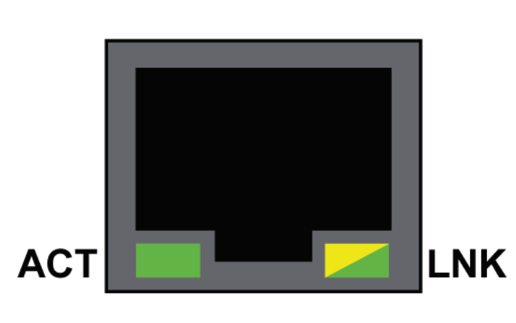
There are two LEDs on each RJ45 port. One is ACT (Active) and another is LNK (Link). The two LEDs can be used to diagnose the state of Ethernet communications over the control ports:
The ACT LED indicates the presence of Ethernet activity on the port.
The LNK LED indicates the existence of an Ethernet link and the link speed.
LED |
State |
Description |
|---|---|---|
ACT |
green |
Link established, no activity. |
green flashing |
Link established, activity detected. |
|
off |
No link established. |
|
LNK |
green |
Link established at speed equal to module maximum capability (1000Mbps). |
yellow |
Link established at speed less than module maximum capability (10/100Mbps). |
|
off |
No link established. |